
Oct 6
2012
Hardware SID Player: An 8-bit computer for playing Commodore 64 music
I like SID tunes – music files written to be played by Commodore 64 computers. Back when the C64 was released they sounded much, much better than any other home computer. Nowadays, well, they’re an acquired taste – here are some to listen to while you read this post:
- Monty on the Run (Ingame) by Rob Hubbard
- Comic Bakery (Loader) by Martin Galway
- Wizball (High Score) by Martin Galway
- Hypa-Ball (Ingame) by Keith Tinman
The really interesting thing about SID tunes is that they are actually computer programs. Back then, there was no standard way to specify how sounds should be played, so each C64 composer had their own way of doing things. Every SID file you download contains not just a list of notes, note lengths, and effects – the actual music – but also contains a “play routine”, which is a computer program written for the 6510 microprocessor which was the heart of a Commodore 64. That means that in order to play SID files, you either need a 6510 processor or you need to emulate one. All SID players (such as SIDAmp for Windows or SIDPLAY for the Mac) are actually Commodore 64 emulators – or, at least, partial emulators.
The other interesting thing about SID tunes is that the sound chip which plays them (called the Sound Interface Device, which gave its name to the tunes) is a mixture of digital and analogue circuitry. Some people claim that the SID is so difficult to simulate that no software-based SID player could recreate the sound of a real chip. I’m not that discriminating – software-based SID players sound just fine to me – but I wanted to see how hard it would be to get sound out of the real thing.
So I built a computer to play SID tunes. Here’s a video of the computer in action.
The rest of this post is about how I made it, and how you can make one too.
Basic theory
To play SIDs using hardware, you fundamentally need three things:
- A 6510 processor
- A SID chip
- RAM to store the song
With the SID tune stored in RAM, it is simply a matter of ensuring the processor, SID chip, and RAM are connected appropriately, then starting the processor and listening to the dulcet tones of the SID. Or so the theory goes.
Unfortunately, these components aren’t super common. The first thing to do was to obtain the chips.
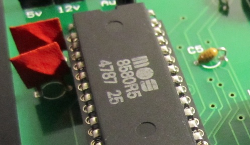
Sourcing the chips
6510 chips are difficult to find. They are a custom version of the popular 6502 microprocessor made specifically for the Commodore 64. Fortunately, it turns out that the majority of SID tunes out there – perhaps all of them – don’t need the special features of the 6510. So I found I could get away with using a plain 6502, which are available on eBay.
The SID chip is a different story. SID chips were made for the Commodore 64, and production of SIDs stopped in 1993. You can find SID chips on eBay, but they are fairly expensive – expect to pay between £10 and £50. Funnily enough, you can sometimes find complete Commodore 64s selling for less than individual SID chips on eBay.
Finally, we need RAM. I chose the 431000 series of RAM chips, because they are readily available on eBay. 431000s contain 128K of RAM, which you’ll note is twice as much as a commodore 64. That’s not a problem: I simply left the highest address line tied to ground, which meant that the upper 64k of RAM on the chip was never accessed and never used.
Designing the circuit
The 6502 processor has an address bus and a data bus. The address bus is 16 bits wide – enough to address 64 kilobytes – and the data bus is 8 bits wide. It is simple enough to hook the processor to the RAM – simply connect each wire of the address bus to the appropriate pin on the RAM, and do the same for the data bus. Make sure to hook the control wires as well, so that the RAM knows whether the processor is reading or writing.
Now the 6502 will be able to read and write to the RAM, but we have two problems. First, how do we connect the SID? And, second, how do we upload SID tunes to the RAM?
Let’s deal with the first problem first: connecting the SID. The basic problem is that we have more than one device which the CPU would like to communicate with – in this case, it’s just RAM and the SID chip. The typical 8-bit solution for this problem is called an address decoder.
My address decoder
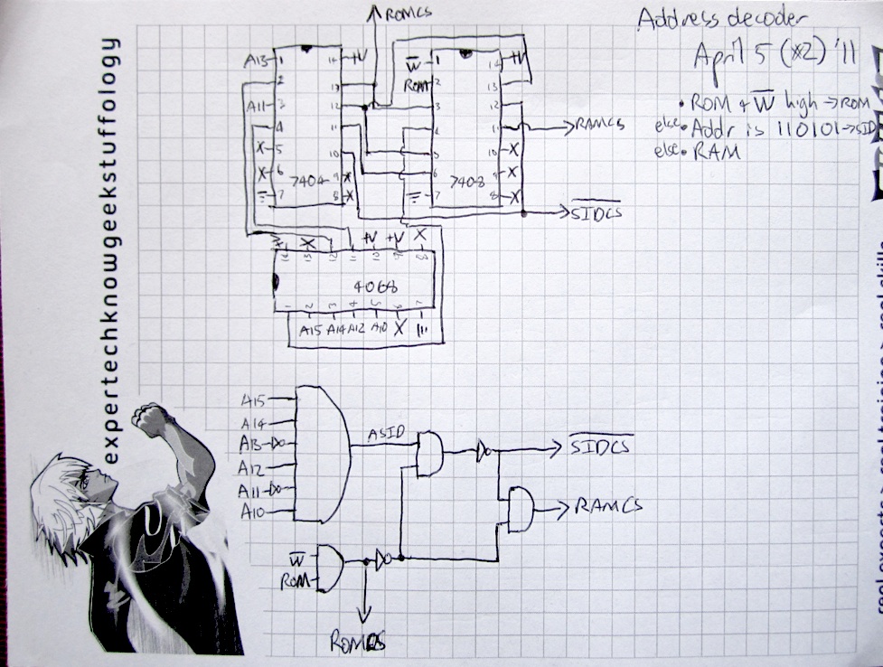
The SID chips sits at addresses 0xD400 to 0xD700 in the Commodore 64 memory (as per the C64 memory map). This simply means that if the C64 wants to access the first byte of SID memory, it will set the 15th, 14th, 12th, and 10th bits of the address bus to “high”, and the remaining bits to “low”. Why those bits? Well, D in binary is 1101 and 4 in binary is 0100, so 0xD400 represented as a 16-bit address in binary is 1101 0100 0000 0000.
That means that our address decoder is conceptually like this:
- If bits 15, 14, 12, and 10 are set to 1, and bits 13 and 11 are set to 0, then access the SID.
- Otherwise, access the RAM.
If you represented this as a logical expression, you could do it like this:
SID = AND (A15, A14, A12, A10, NOT(A13), NOT(A11))
Basically, if that big expression is true, then select the SID. If it’s false, select the RAM.
There are chips which will do this for us. The 74HC04 hex inverter is 6 NOT gates in one chip, and the 4068 is an AND gate with 8 inputs, i.e. if all 8 inputs are true then the output is true. So we simply connect A13 and A14 to two of the NOT gates on the 74HC04, and connect the outputs of the NOT gates, as well as A15, A14, A12, and A10, to the AND gate. We then have two “spare” inputs to the AND gate which I just connect directly to +5V. And voila – an address decoder! We can connect the output of this address decoder directly to the SID and RAM chips! Well, almost – it turns out that the “chip select” lines on the SID chip and on the RAM are “active low”. So we connect the SID chip to the address decoder via a spare NOT gate, and connect the RAM to the address decoder directly.
If you looked at the C64 memory map, you will see that this address decoder isn’t much like a real C64 – in some cases, it will access RAM when it should be accessing a device. It turns out that this doesn’t matter: most SIDs make use of these other devices, so it doesn’t matter that they’re not there. This makes sense conceptually – why would a SID tune need to access stuff related to the display, or the cassette drive? (This isn’t strictly true actually – but I’ll get back to this later.)
Also, this type of address decoder is oldschool even for the C64 era. The C64 used a custom chip for its address decoder, and normally one would use a CPLD or similar. I did it using discrete logic for fun.
Now for the next problem: getting SIDs into the system, and running the 6502.
Interlude: SID upload and timers
We still have three problems to solve.
First is the problem of getting SID tunes into the RAM, as alluded to above. As currently designed, the system doesn’t have any input devices – so there is no way to program it.
Second is related to things the 6502 needs to run. At the very least, it needs a clock signal. The Commodore 64 ran at 1 MHz (or a little bit less in PAL regions) so we need something that will supply a 1 MHz clock. SID tunes themselves tend to be tied to the display’s refresh rate – which means that we also need some kind of interrupt occurring at 50 Hz (for PAL regions) or 60 Hz (for NTSC regions).
I solved all of these problems using a microcontroller – specifically, an 8-bit PIC.
The second problem – timers – is the simpler one. 8 bit PIC microcontrollers have a PWM module which can be configured to supply a 1MHz signal easily enough. This signal can be directly connected to the 6502’s clock input. The other frequency – 50 or 60 Hz – is a bit low for the PWM module, but is easy enough to do in software. We end up with two wires connecting the PIC to the CPU: one to the clock pin, for the 1 MHz signal, and the other to the interrupt pin, for the 50 or 60 Hz “vertical blank interrupt” which is what SID tunes generally use.
The other problem – getting SID tunes into RAM – is a nightmare.
The simplest solution is simply to connect the PIC to RAM. That would mean connecting the PIC to all 16 address bus lines, and all 8 data bus lines. The PIC I chose (an 18F14K50) doesn’t have enough outputs to do this, but that’s not such a difficulty because there are chips which do a serial-to-parallel conversion, such as the 74HC164 (search “74hc164 PIC” for some simple examples). However, there is a much bigger problem with this simple solution, and that is that most 6502s can’t tristate their address bus.
Tristating the address bus
The problem is that we would want the PIC to put information onto the address bus – that is, set some bits to “high” and some bits to “low” as it uploaded the SID tune to RAM (and note that I haven’t actually got the SID tune to the PIC, either – that’s another problem). The problem with doing this – i.e., putting voltages onto the address bus – is that the 6502 expects to be the only thing that can do that. If two devices do it, then it can result in damage to the 6502.
Some processors can avoid this by “tristating” their address bus pins, which means they can essentially disconnect themselves from the bus, putting themselves into a state called “High-Z”. This prevents damage and lets other devices control the bus. However, the 6502 can’t do this. Interestingly enough, the 6510 CAN do it – it’s one of the few differences between the 6510 and the 6502. However, I was stuck with a 6502 and had to work around this problem. I can’t decide whether my solution is good, or very horrible.
My solution uses the PIC to manually clock the 6502 “blind”, supplying a program that instructs the 6502 to write its own SID file to RAM. Here’s how it works:
- I connect the PIC to the data bus. This is totally acceptable, because all 6502s can tristate the data bus.
- I then use the PIC to start the 6502, raising and lowering the PIC’s clock line so that the 6502 runs for exactly 6 cycles. This is the number of cycles that the 6502 requires to boot up, according to the data sheet.
- The first thing that the 6502 does is attempt to read two bytes from addresses 0xFFFC and 0xFFFD. These two bytes are the “reset vector” – an address to jump to to begin executing code when the 6502 is reset. In a Commodore 64, these bytes are stored in ROM. For my computer, I use the PIC to put the special address 0xFF00 on the data lines, instructing the 6502 to begin executing code at address 0xFF00.
- The 6502 then dutifully puts 0xFF00 on the address bus lines and attempts to read a byte on the data bus. This is the first byte of code. I use the PIC to put 0xA9 on the data bus. This is the 6502 instruction LDA, which tells the 6502 to store the next byte that it reads in register A.
- The 6502 then reads another byte, which is the argument to LDA. I use the PIC to put the first byte of the SID program on the data bus.
- The 6502 then reads another byte, which is the next code instruction to execute. I use the PIC to put 0x8D on the data bus. This is the 6502 instruction STA, which tells the 6502 to store the value of register A in memory (you can see where this is going).
- The 6502 then reads another two bytes. These form the 16-bit parameter to STA, which is the address to store the value in register A. I put the starting address of the SID program on the address bus.
- I repeat steps 4 to 7 until all bytes of the SID program have been stored.
This method is sort of horrible, but it’s also quite neat, because it means that I don’t have to figure out a way to connect 16 lines from the PIC to the address bus (it would have been possible, using shift registers and special chips which can essentially tristate the bus externally, but messy).
The main issue with this method is that the PIC can’t manually clock the 6502 fast enough to do all of this at 1 MHz. In fact, it runs several times slower than that. This wouldn’t be a problem, but the 6502 uses dynamic RAM for its registers – clock it too slowly, and it forgets the values in its registers. Fortunately, the PIC could manually clock the 6502 fast enough that this wasn’t a problem.
The second issue is that I had to add a couple of wires to my address decoder. The new logic for the address decoder looks like this:
- If the PIC has requested control, and the CPU is trying to read data, disable both the RAM and the SID.
- Otherwise, if it’s a SID address, enable the SID.
- Otherwise, enable the RAM.
The beauty of this approach is that the CPU can be reading from the PIC, and writing to the RAM – until the SID tune has been fully uploaded, and then the PIC can essentially disconnect itself from the system entirely.
Playing the tunes
We still haven’t got SID tunes into the PIC. But not to worry – there are plenty of ways to get data into a PIC. One of the simplest is to use the PIC’s serial port. I decided to be a bit fancy about this and use Bluetooth. There are pre-made modules on eBay, selling for about 5 US dollars, which provide a Bluetooth serial interface – hook the serial part up to the PIC, and you can connect from a PC.
Then it was just a matter of writing a custom program for the PIC, defining a protocol for describing the SID tune over the serial interface (including, for example, the speed of playback – 50 Hz or 60 Hz?), and writing a program for my laptop which would upload SIDs via this interface, and the board was almost ready to go.
There was one last thing. SID files don’t play by themselves – instead, they supply an address in memory called the “play routine” which should be called at either 50 Hz or 60 Hz. As described above, I had connected the PIC to the 6502’s interrupt pin, so that the PIC could cause a 6502 interrupt at the appropriate time. My solution here was to write a small piece of 6502 code which I uploaded at the same time as the SID. The code contained a “cold start” routine, run once to initialise the SID, and also an interrupt handling routine, which simply called the SID play routine. (This code is contained in libsid.py avilable below, if you’re interested.)
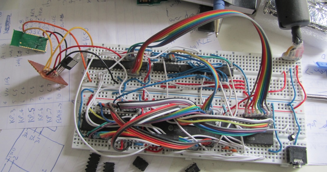
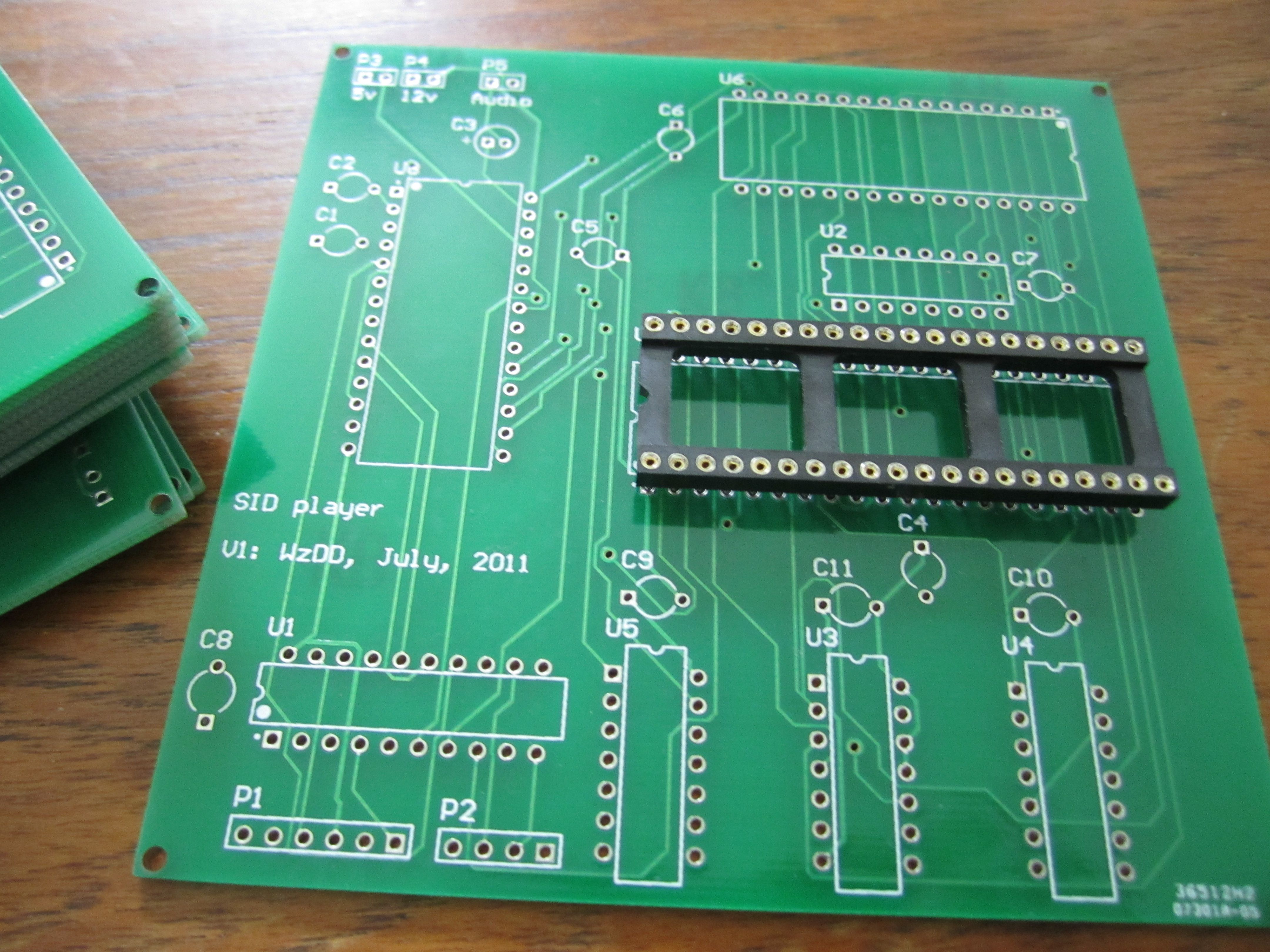
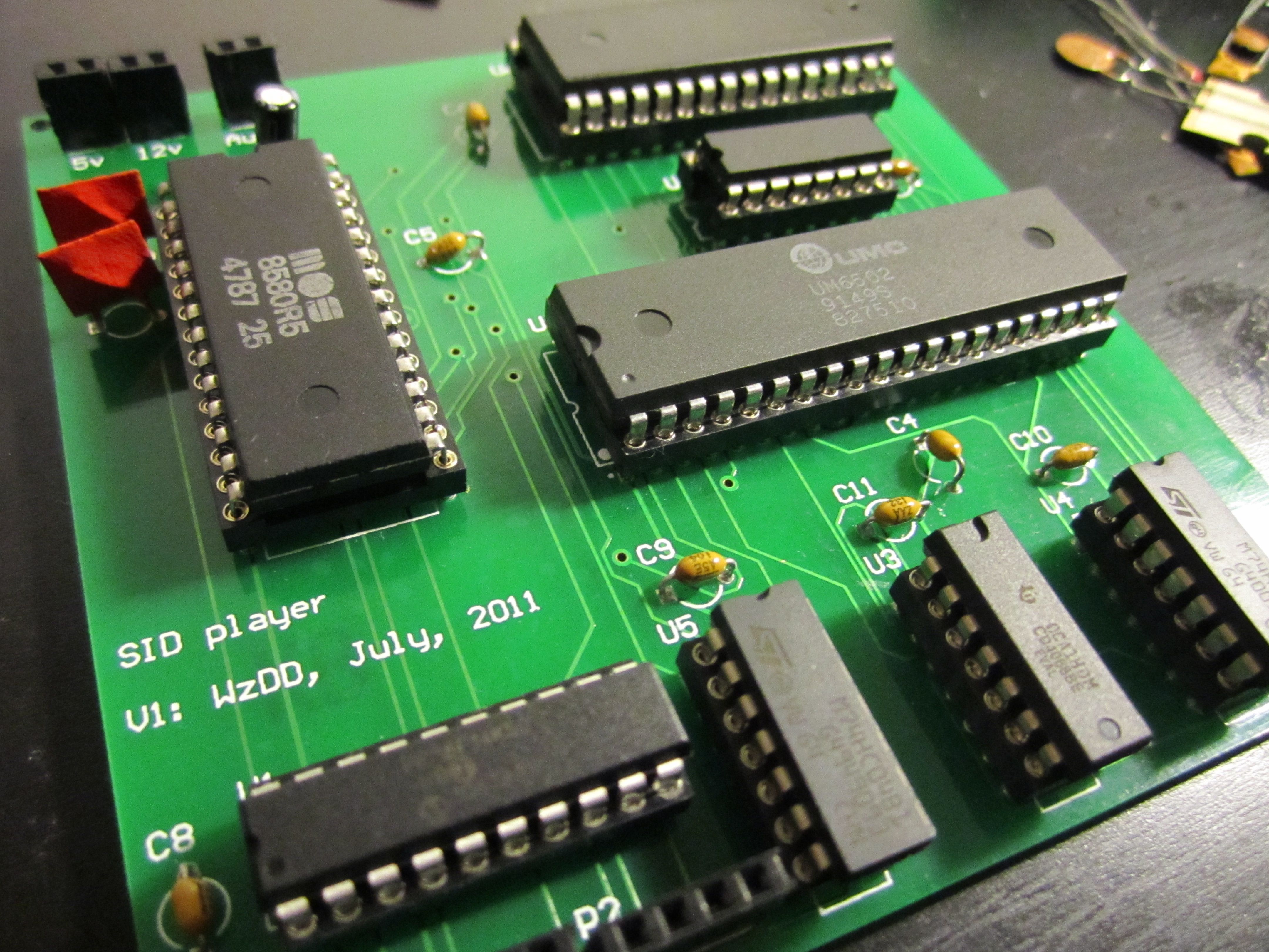
Circuit design and PCBs
As you can probably imagine, I wasn’t keen to stay with the breadboarded prototype. I wanted real circuit boards. There are plenty of places which will print short-run circuit designs very cheaply. I chose ITead Studio. I designed my board using Altium, and after one false start with the Gerbers, and a long wait, my PCBs came back! It was time to get soldering.
RSIDs and other limitations
The player has a bunch of problems.
The first, and simplest, is that I made a couple of mistakes on the PCB – essentially, I forgot to add a couple of connections. These were easy to fix with wire, but were a bit embarrassing.
The second problem is a bit more serious. There are two types of SID files. The original type, now called PSID (“Play SID”, named after one of the first SID players), contains a play routine as described above, and a bit of meta-data describing the frequency at which the play routine should be called. However, people started to find this format limiting, and so the RSID (“Real SID”) was born.
The RSID doesn’t include a frequency at which the play routine should be called. Instead, it contains a setup routine which programs one of the Commodore 64’s timer chips to deliver a custom playback speed – or it simply uses its own delay loop, or does whatever else it likes: RSIDs assume that the system they are running on is a pretty-much complete Commodore 64. This obviously poses some problems for my SID player.
The RSID problem probably isn’t as bad as it sounds. I suspect that some static analysis of RSID files will reveal that actually they only use a few C64 features. I could write a program which analyses the files and works out what features they use and how they use them, and then convert them into something appropriate for my SID player.
For example, imagine that an RSID starts by programming one of the Commodore 64 timers to interrupt at 25 Hz. It should be possible to recognise this code using static analysis. I could then simply instruct the SID player to run the appropriate code 25 times a second – in effect, converting RSIDs into PSIDs. I haven’t yet attempted this, because there are many, many PSIDs – most C64 game music is PSID, for example.
Source code and Gerbers
All my code is open source and I hereby place it into the public domain. You can do whatever you like with it, but don’t expect that it will do anything at all and certainly don’t expect support. Feel free to email me, though – I’ll help whenever I can.
- Gerbers
- Altim (and component files)
- Python code (instructions for use are at the bottom of http://lardcave.net/6502sid/)
- Code for PIC18F14K50 (including Makefile, C code, an hex file) – should be portable to most 8-bit PICs.
If you do assemble one yourself, please do get in touch as there are a couple of things I haven’t touched on here (most importantly, an amplifier for the SID output) which could otherwise ruin your day.
Please do also let me know if you spot a mistake in this write-up. I’m sure there are at least a couple.
Good luck!