2018
Reading and writing Dreamcast Visual Memory Units with an Arduino
A long time ago I wrote a post on accessing Sega Dreamcast VMUs. This is an update to that post which significantly improves the read support to the point where it works reliably using a standard Arduino.
I should add that I thought my read support was reliable last time, until I got reports from people who were having trouble with it and bought a few more VMUs to test with. I am quite a bit more confident in the new version, because it doesn't take any shortcuts: the previous version used "dead reckoning" for some parts of the protocol, but this version is more than fast enough to keep up with the VMU without making any assumptions about its state.
This post is probably even less accessible and interesting than most of my code posts, though if you're into assembly language optimisation then you'll love it. If not, the summary is that it's practical to use an unmodified 16MHz Arduino to receive Maple bus data (and even arbitrarily-long packets) by running it as a logic analyser running at about 5 million samples per second. The rest of the post is about the optimisation story that got me to this point.
What's a VMU?
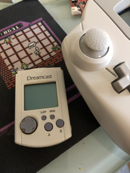
A Visual Memory Unit (Visual Memory System in the USA) is primarily a save game card for Dreamcast systems, but it also has a little LCD and buttons. They look like this:

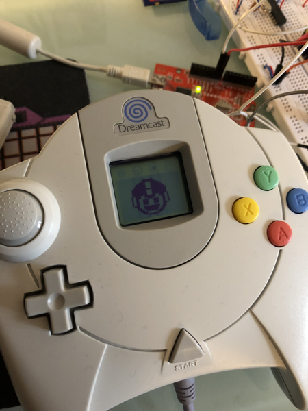
VMUs slot into the Dreamcast controller and can display images during gameplay.

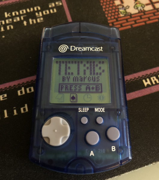
From my perspective, the most interesting thing about them is that they also function as completely self-contained handheld gaming units (for some reason):

Actually, that's a lie. The most interesting thing about them is that it seemed like it should be possible to read and write data on them using nothing more than a Dreamcast controller and an Arduino. This post is mostly about how you do that.
Background
VMUs communicate with the mothership (which is usually a Dreamcast) using a protocol called Maple. This is pretty damn fast (for an glorified memory stick), running at 2 megabits per second, sender clocked. Here's Marcus Comstedt's writeup of the wire protocol. The summary is that it uses two wires (plus power and ground), with the data and clock lines alternating every transition, and signals changing at speeds of up to 0.5ms (or even faster, it turns out, when the VMU is in control).
Receiving VMU-clocked data with an Arduino
There are two major VMU hardware hacking efforts that I've found, Marcus Comstedt's and Dmitry Grinberg's. (Both of these sites are fantastic.) Marcus and Dmitry point out that sending data to the VMU is very easy, because you can send at whatever speed you like. However, receiving data is rather more difficult, as the VMU controls the speed.
In pseudocode, receiving this data would look something like this, assuming the clock and data pins are called PIN1 and PIN5 (following Marcus' naming scheme):
1. If there's no more data to receive, finish.2. Wait for PIN1 to go LOW.
3. Read and store the bit from PIN5.
4. Wait for PIN5 to go HIGH, if it isn't already.
5. Wait for PIN5 to go LOW.
6. Read and store the bit from PIN1.
7. Wait for PIN1 to go HIGH, if it isn't already.
8. Go to step 1.
This pseudocode receives two bits, and takes into account the fact that clock and data pins switch roles every bit. On an Arduino running at 16Mhz, we have 16 cycles per millisecond. At 2Mbits/sec, that means that at the very most we have to complete the above pseudocode, to receive two bits, in 16 cycles.
No problem, right?
Doing the obvious thing (and failing)
The obvious thing to do is something like this, using slightly-abridged AVR assembly language with labels matching the pseudocode above:
1:
	; TODO - check end condition
2:
	SBIC PIN1		; skip the next instruction if PIN1 is low
	RJMP 2b			; go back and read PIN1 again
3:
	SBIC PIN5		; skip the next instruction if PIN5 is low
	OR data, 1		; Store the bit
	LSL data, 1		; Shift the data register left by 1 to receive the next bit
4:
	SBIS PIN5		; skip the next instruction if PIN5 is high
	RJMP 4b			; PIN5 was low, so try again
5:
	SBIC PIN5		; skip the next instruction if PIN5 is low
	RJMP 5b			; PIN5 was high, so try again
6:
	SBIC PIN1		; skip the next instruction if PIN1 is low
	OR data, 1		; Store the bit
7:
	SBIS PIN1		; skip the next instruction if PIN1 is high
	RJMP 7b			; PIN1 was low, so try again
8:
	ST X+, data		; Write the data to memory
	LDI data, 0		; Clear data
	RJMP 1b			; go back to start
Straightforward, but rather problematic:
- We're only writing two bits per byte, which sucks, but we can fix it by unrolling the loop four times.
- We take different numbers of cycles to perform the different steps, and particularly writing the data to memory and jumping back to the start of the loop is very slow (4 cycles, or 1/4 of a millisecond). This matters because even if the VMU operates at 2Mbits/sec on average, not all cycles are the same length.
- More importantly, it takes 18 cycles, which is too slow.
- Even if it were faster, it would still need to check the end condition (at the moment it's an infinite loop).
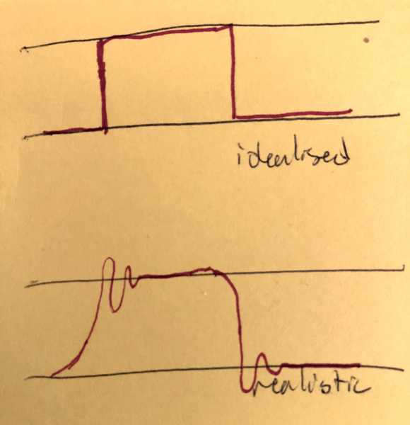
Without going into too much more detail here, it's possible to get a loop like the one above down to 16 cycles, but it doesn't seem that easy to make it significantly better than that. As discussed above, 16 cycles for two bits is the bare minimum, but practically speaking 16 cycles is too slow: firstly, the VMU is sometimes faster than 2Mbits/sec, and secondly even if it were not, it's easy for transmitter and receiver to get out of phase in such a way that the receiver misses some bits:

Dmitry's approach to this problem is to use a significantly faster processor, an STM32 clocked at 80MHz, but I wanted to stick with Arduino, so couldn't follow his lead.
Marcus had a different solution: you don't actually need to implement the Maple protocol in real time. All you need to do is make sure you capture every signal change on the two pins. If you store the complete set of signal changes, you can do the decoding "offline", after the receive has finished. In effect, you make a special purpose logic analyser to capture the communication, and then decode it later.
Arduino as logic analyser
The great thing about the logic analyser approach is that it's so conceptually simple. Here is the pseudocode:
1. If there is no more data to receive, finish.2. Read and store PIN1 and PIN5.
3. Go to step 1.
Unfortunately, the simplicity comes at a cost. Every bit involves two signal transitions, and we have to capture both of them. Since one bit arrives every half millisecond, that means we have a quarter of a millisecond to read and store the two samples -- or just four Arduino clock cycles.
Marcus used a special hardware device as his logic analyser, but I didn't have one of those.
Here is the naive Arduino code to do the above, annotated with the number of clock cycles each instruction takes. I've also started using real registers -- here the working register is r18 (which is a "scratch" register for AVR):
1:
	; TODO check end condition
2:
	IN r18                       ; 1 cycle: read both CLOCK and DATA
	ST X+, r18                   ; 2 cycles: write clock and data to memory
3:
	RJMP 1b                      ; 2 cycles: loop
We can immediately see the problem with this -- it's too slow! Reading, writing, and looping take five clock cycles, and we have a budget of 4. It's also rather wasteful, because we're using a whole byte for clock and data lines. And on top of all that, we still haven't checked the end condition, so this loop will run forever.
What happens if we put more bits into the data word, and move things around so that we have an equal number of cycles for each sample?
1:
	; TODO check end condition
	SWAP r18                      ; 1 cycle: swap upper and lower nybbles of r18
	IN r19                        ; 1 cycle: read clock and data into r19
	OR r18, r19                   ; 1 cycle: r18 = r18 | r19
	ST X+, r18                    ; 2 cycles: write clock and data to memory
	IN r18                        ; 1 cycle: read clock and data into r18
	RJMP 1b                       ; 2 cycles: loop
This is much nicer, though it's harder to understand. We now use two registers, r18 and r19. We store two samples in one byte by using the SWAP instruction, which swaps the lower four bytes (one nybble) and the upper four bytes. We just need to ensure that we have no more than four bits of input (we only have two, CLOCK and DATA) and that these bits show up only in the lower four or upper four bits.
This still isn't good enough, though -- four cycles per bit is too slow, practically speaking, even if we were checking the end condition, which we aren't. Also, since we only have two bits of data, shouldn't we be storing four samples per byte? Packing extra samples into a byte is important because the Arduino only has 2 kilobytes of RAM. At two bits per byte, that gives us an absolute maximum message length of 512 bytes -- but practically speaking, we get far fewer than that.
Without going into the details, it's possible to store four samples per byte if you ensure that your inputs are in the lowest two bits by using LSL (shift register contents left by one bit) and SWAP.
Hardware hacking
After some experimentation, I had an implementation that could read four samples in 16 cycles, check an end condition, and store all four samples in one byte. But it was still too slow: as discussed above, to accurately receive 2Mbits/sec, we must be faster than 2Msamples/sec, not exactly the same speed.
But then I thought: we're stuck with the Arduino, but we can still make hardware changes. What if we connected the data and clock lines to multiple places on the Arduino? Specifically, what if we connected them twice: in the lowest two bits of one port (PORTB), but also on another port (PORTC), two bits further up? If we did that, we wouldn't need to do so much shifting and swapping, because the inputs would be, in effect, pre-shifted.
After making this change, and doing a bit of experimentation, I ended up with the following. The comments show the cycle count followed by positions of each sample across the three registers it uses.
.macro read_four_samples
	IN r18, IOM2       ; 1; ----51-- ------51 ----51--
	OR r18, r19        ; 1; ----5151
	SWAP r18           ; 1; 5151----
	IN r19, IOM1       ; 1; 5151---- ------51
	OR r18, r20        ; 1; 515151--
	OR r18, r19        ; 1; 51515151
	IN r19, IOM1       ; 1; 51515151 ------51
	ST X+, r18         ; 2; -------- ------51
	IN r20, IOM2       ; 1; -------- ------51 ----51--
.endm
A couple of comments on this:
- It reads one sample every 3 cycles, for an effective sample rate of 5 1/3 MSPS, which is sufficient.
- It uses three registers, the contents of which are described in the comments.
- The delay between each sample being taken is equally balanced, assuming the thing following the macro is something that takes two cycles (i.e. an RJMP)
To use the macro, unroll it several times. Because the macro both begins and ends with an IN (which takes a sample), you have two spare cycles between each macro invocation to do 'housekeeping'. Below, we use this feature to bail out of the infinite loop if we run out of free space:
1:
	read_four_samples

	; read second byte:
	NOP
	NOP
	read_four_samples

	; read third byte:
	NOP
	NOP
	read_four_samples

	; read final byte
	DEC r30                ; have we run out of space?
	BREQ _maple_rx_end     ; yes, stop writing
	read_four_samples

	; lead-out: 2-cycle jump to read the next 4 bytes.
	RJMP 1b
Supporting large packets
As discussed, the Arduino I'm using has 2KB of RAM, and I'm sampling at over 5MSPS. This gives me approximately the world's worst logic analyser, running out of memory in about one-nothingth of a second. Although in theory you can store a sufficient number of samples in 2KB, in practise the VMU spends a lot of time waiting around doing nothing between blasting out small chunks of reply, which means a lot of sample space is occupied by this dead air.
Fortunately, all commands which produce long replies from the VMU are non-destructive: they're device IDs, or flash reads. So the solution is to repeat the command, and ignore everything we've already seen on the repeats. This means we can build up the complete response one 2KB chunk at a time.
How do you know how much to ignore? You count sample periods. If the first reply produces 2048 samples, then just wait 2048 sample periods the next time.
This obviously requires that the VMU be very deterministic in its timings, which, fortunately, it is. It doesn't seem like this approach should work nearly this easily, but it does.
It still sucks!
This support is far from perfect -- I still get bad reads somewhat frequently. This is less of a problem than you might expect, because the Maple library (and in particular the VMU dump program) reads multiple times until it gets two which are the same. This seems stable (if slow). There's definitely room for improvement here: the first thing I'd like to try next is improving the hardware. I'm using a breadboard to split my clock and data signals across two pins, and I suspect that this introduces extra capacitance and/or ringing which interferes with the sampling.
Read and write support is also very slow. There is some low hanging fruit here -- a big reason for the slow-down is that each transaction transfers 1.5KB of data from the Arduino to the Python library, and this could be slimmed down significantly (by having the Arduino translate the samples into bytes).
To be honest, I'm surprised that this was practical at all.
Getting the code
Get it from$ git clone https://github.com/nfd/arduino-maple
You'll need Python 3 and the pyserial library:
$ pip3 install pyserial
Running the code
Build and upload the binary to your Arduino. You will need to edit the serial port in the Makefile.
$ make upload
Displaying an image
See the README and vmu_image.py for (very simple) image format.
$ python3 vmu_image.py -p /dev/tty.usbserial megaman.txt
Uploading a VMU game
$ python3 vmu_flash.py -p /dev/tty.usbserial tetris\ vmu.vms
Tetris is available from Marcus' site.
Reading VMU data
$ python3 vmu_dump.py -p /dev/tty.usbserial vmudump
Use as a library
Have a look at the MapleProxy class in maple.py. The utility programs above are good examples of how to use the library.
